




What You Need For This Tutorial
- Raspberry Pi 4 – Buy Here
- Ice Tower – Buy Here
- Micro SD Card – Buy Here
- Raspberry Pi Power Supply – Buy Here
- I2C 128×64 OLED Display – Buy Here
- 4 Wire Female to Female Jumper Cable – Buy Here
Connecting Your OLED Stats Display To Your Raspberry Pi
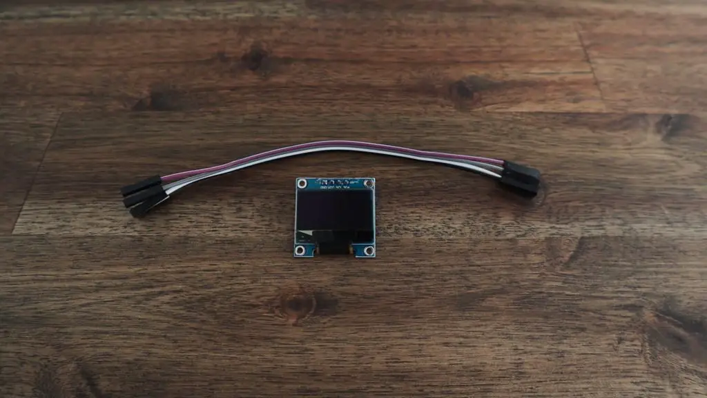
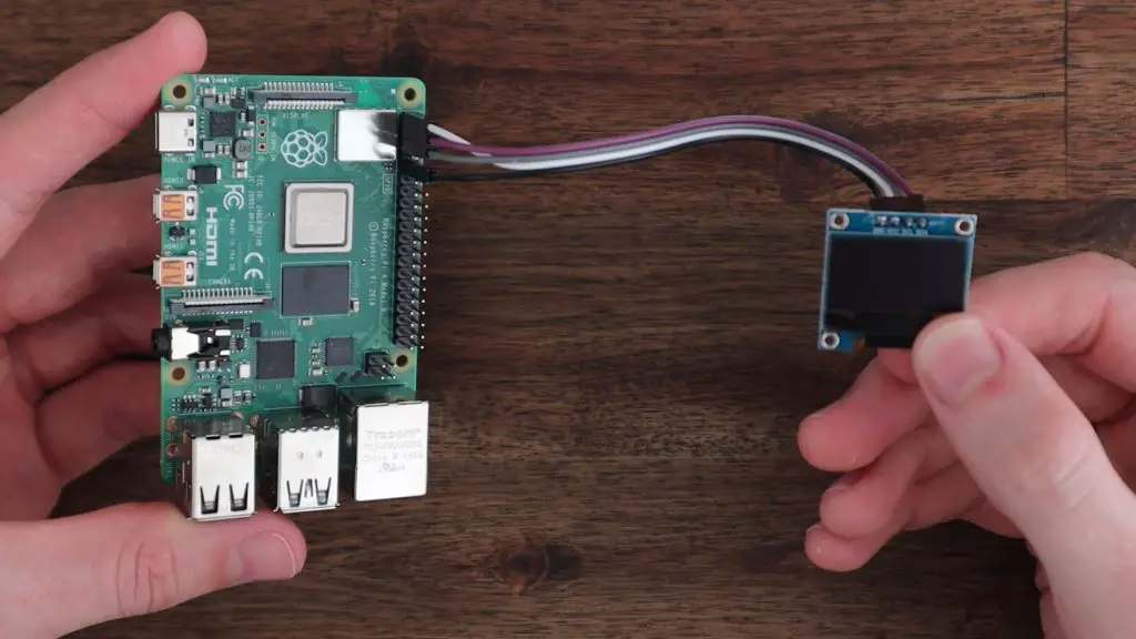
To start out, we’re going to go through the same process to connect the OLED stats display to our Raspberry Pi. To do this, you’ll need a 4 wire female to female jumper cable. The colours don’t matter, they’re just there to help you keep track of which wire goes to which terminal.
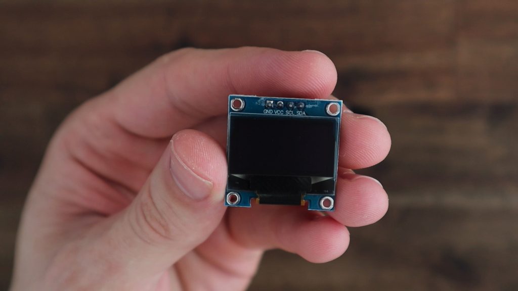
The OLED display’s terminals are labelled on the front, which seems to confuse a lot of people since the pins extend out the back of the display.
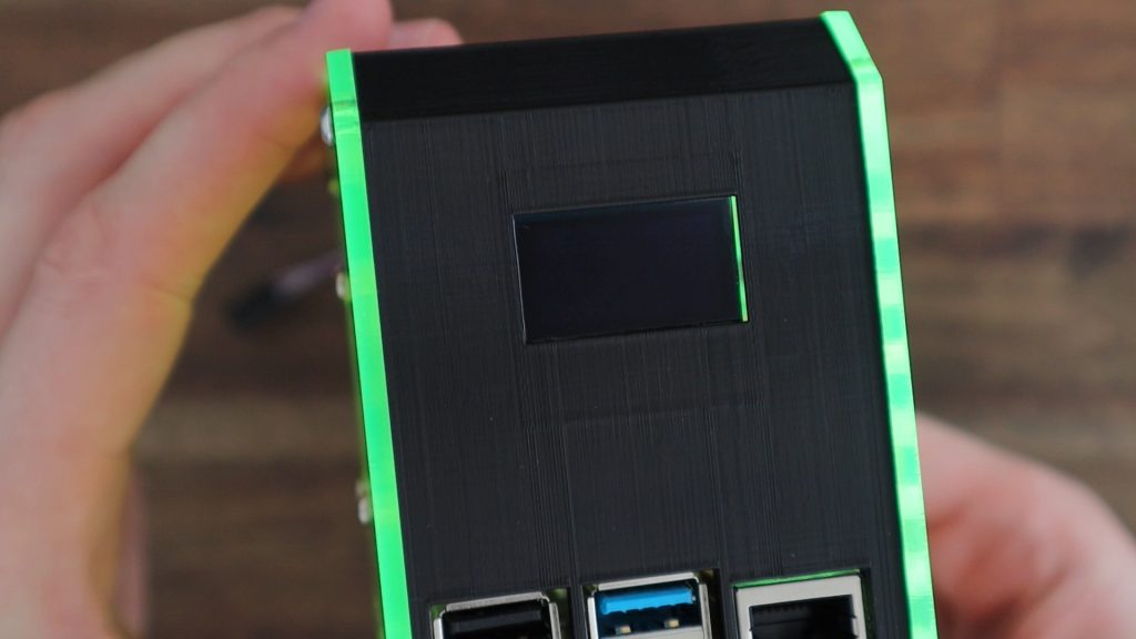
This is especially difficult to spot once the display has been installed into the case and the front area of the display is no longer visible. So make sure that you jot them down before installing the display into a case or holder.
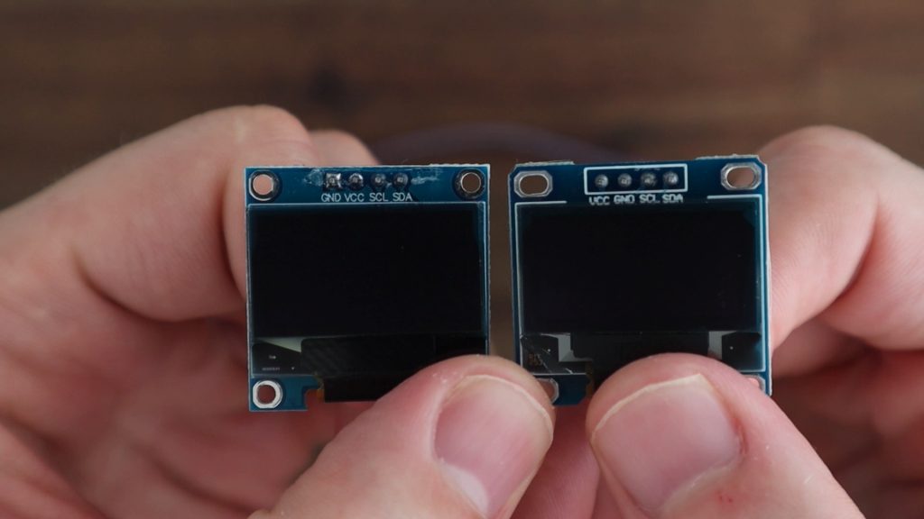
The pin arrangement is most commonly GND, VCC, SCL and SDA. Don’t just copy this arrangement, make sure you check your own display as there are versions of these displays with the VCC and GND pins switched around. If you connect power to them incorrectly they’ll most likely be damaged and will no longer work, even if you correct the wiring afterwards.
Plug your ribbon cable into these four pins and then take note of which colour you’ve got connected to which pin. If you’re installing the display into your case before connecting it to your Raspberry Pi then it’s a good idea to write down which colour is connected to which pin so that you don’t forget.
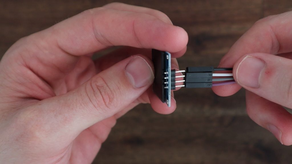
Next we can plug the other ends of the jumpers into the Raspberry Pi’s GPIO pins. The Pi’s GPIO pinout diagram can be found quite easily online and is available from the official website.
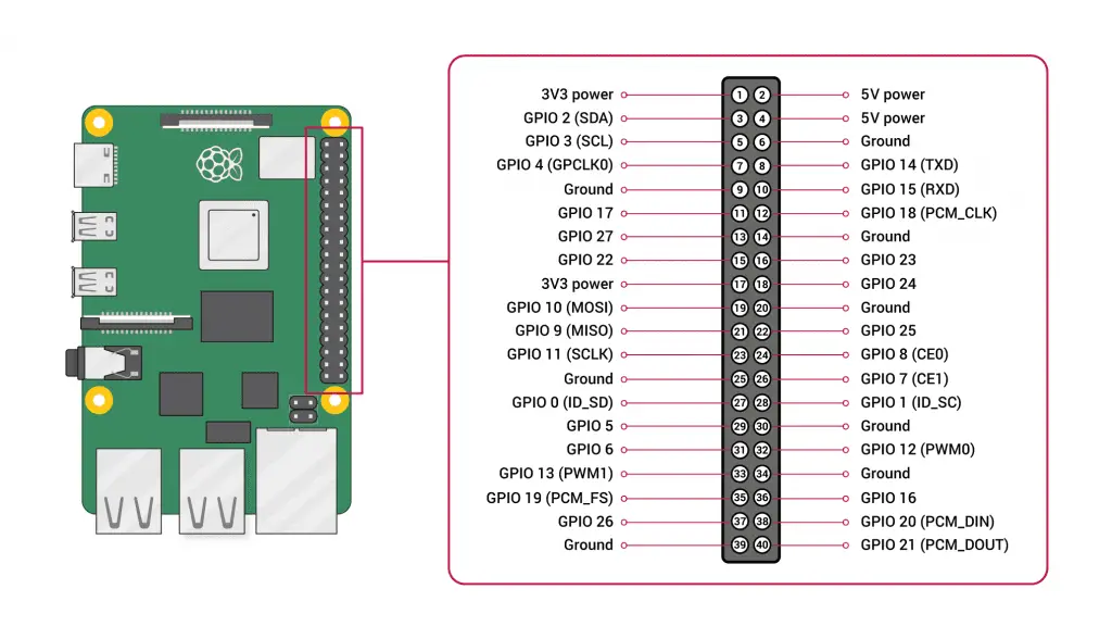
Make sure that your Pi is off and the power is disconnected before plugging or unplugging jumpers from the GPIO pins. You don’t want to short a connection or plug a lead into the incorrect pin by mistake and not have a chance to check your connections before powering it up.
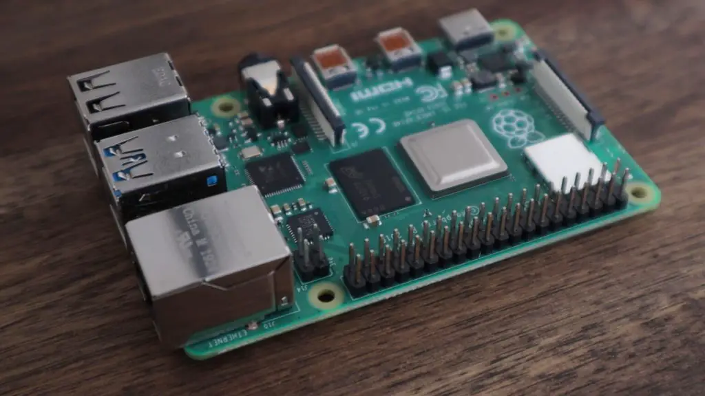
You’ve got a few options for the GND and VCC jumpers. I usually plug the GND jumper into Pin 9 (you can use any pin labelled GND). And I plug the VCC jumper into Pin 1, which is a 3.3V power pin. These displays can operate on 3.3V or 5V inputs, so any power pins on the Pi’s GPIO header will work.

Next, we need to connect the communication jumpers SCL and SDA, which just get plugged into the corresponding GPIO pins. Plug SCL into Pin 5 and SDA into Pin 3. Don’t get confused between the GPIO numbers and the Pin numbers, ignore the GPIO numbers on the diagram and just go by the SDA and SCL labels and the corresponding pin numbers.
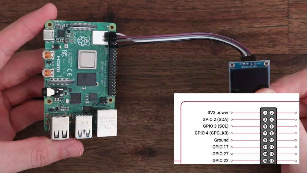
Check all of your connections again and you’re then ready to power your Pi up and get started with programming the display.
Programming The OLED Stats Display
Now that we’ve got the display connected, we can look at programming our Raspberry Pi to display the performance stats. I’m going to be doing this on a fresh install of Raspberry Pi OS Bullseye by using the Raspberry Pi Imager utility to flash the operating system image to a new microSD card.
Put the SD card into your Pi’s SD card slot and plug in your power adaptor. Once you’ve booted up your Pi, you should be on the Raspberry Pi OS desktop. It’s possible to do this installation on a headless Pi as well using the same steps.upgrade
sudo apt-get updatesudo apt-get full-upgrade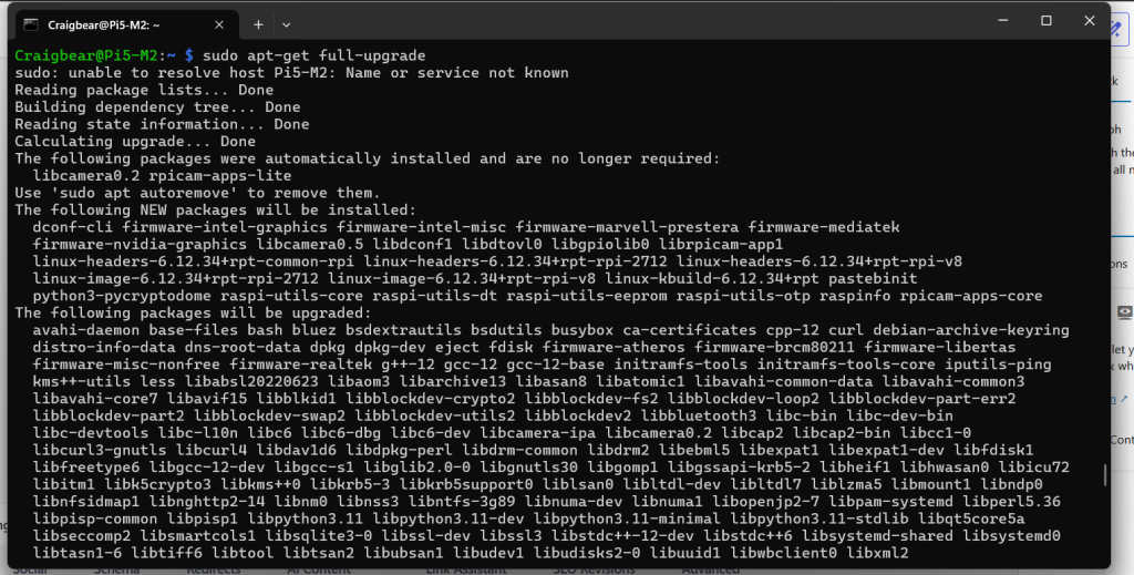
sudo reboot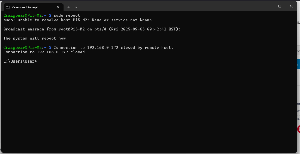
sudo apt-get install python3-pip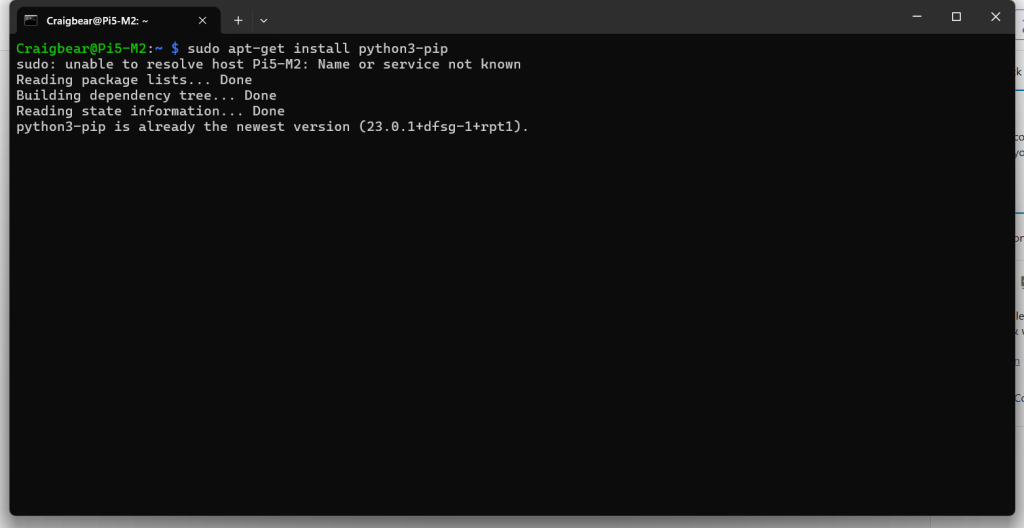
sudo pip3 install --upgrade setuptools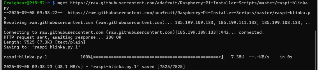
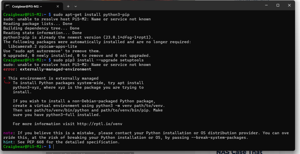
to get arount the error this command